| REF |
PART TYPE |
COMMENT |
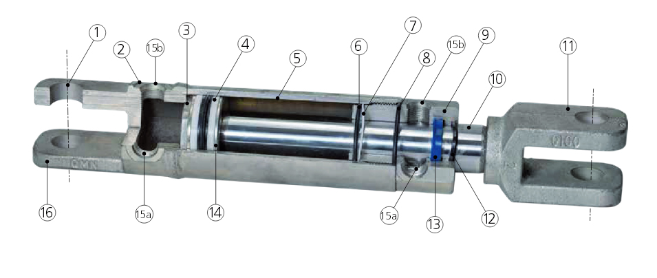
| 1 |
Pins and Clips |
1045 Zinc Plated Pins and Clips. |
| 2 |
Base |
The fixed end of the cylinder. SG Iron on AG Series and Steel in the Industrial Series. |
| 3 |
Piston Retention |
Piston Retention |
| 4 |
Piston Seal |
Kastas High Pressure 3 Piece Piston Seal complete with Wear Bands. |
| 5 |
Bore |
The internal diameter of the hydraulic cylinder. |
| 6 |
Gland O-Ring |
Gland O-Ring. |
| 7 |
Seal Backup |
Seal Backup. |
| 8 |
Weather Seal |
Weather Seal. |
| 9 |
Gland |
CNC, 1045 Internal Gland. Supports the rod and deals the cylinder at the rod end. |
| 10 |
Rod |
1045 Hardened, Chromed. The internal reciprocating member of the cylinder, connected to the piston at one end. Also referred to as the shaft. |
| 11 |
Rod Clevis |
SG Iron. U shaped coupling, with pin holes, intended to accept a male mount in the gap. This Clevis moves with the rod. |
| 12 |
Rod Wiper |
Kastas Rod Wiper. |
| 13 |
Rod Seal |
Kastas Rod Seal. |
| 14 |
Piston |
Transmits the hydraulic pressure to the rod, to create a pulling or pushing force. IND Series has a wider piston compared to the AG Series. |
| 15 |
Ports |
The connection point between cylinder and the system. Ports are welded on the industrial series and threaded into the gland on the AG series. |
|
15a |
Port Position ‘A’ : 90 degrees to the pin. |
|
15b |
Port Position ‘B’ : ports in line with the pins. |
|
15a + 15b |
Port Position ‘D’ : Dual ports. Ports A & B at both ends. |
| 16 |
Rear Clevis |
Cast Steel. U shaped coupling, with pin holes, intended to accept a male mount in the gap. The Rear Clevis is fixed with the base. |